
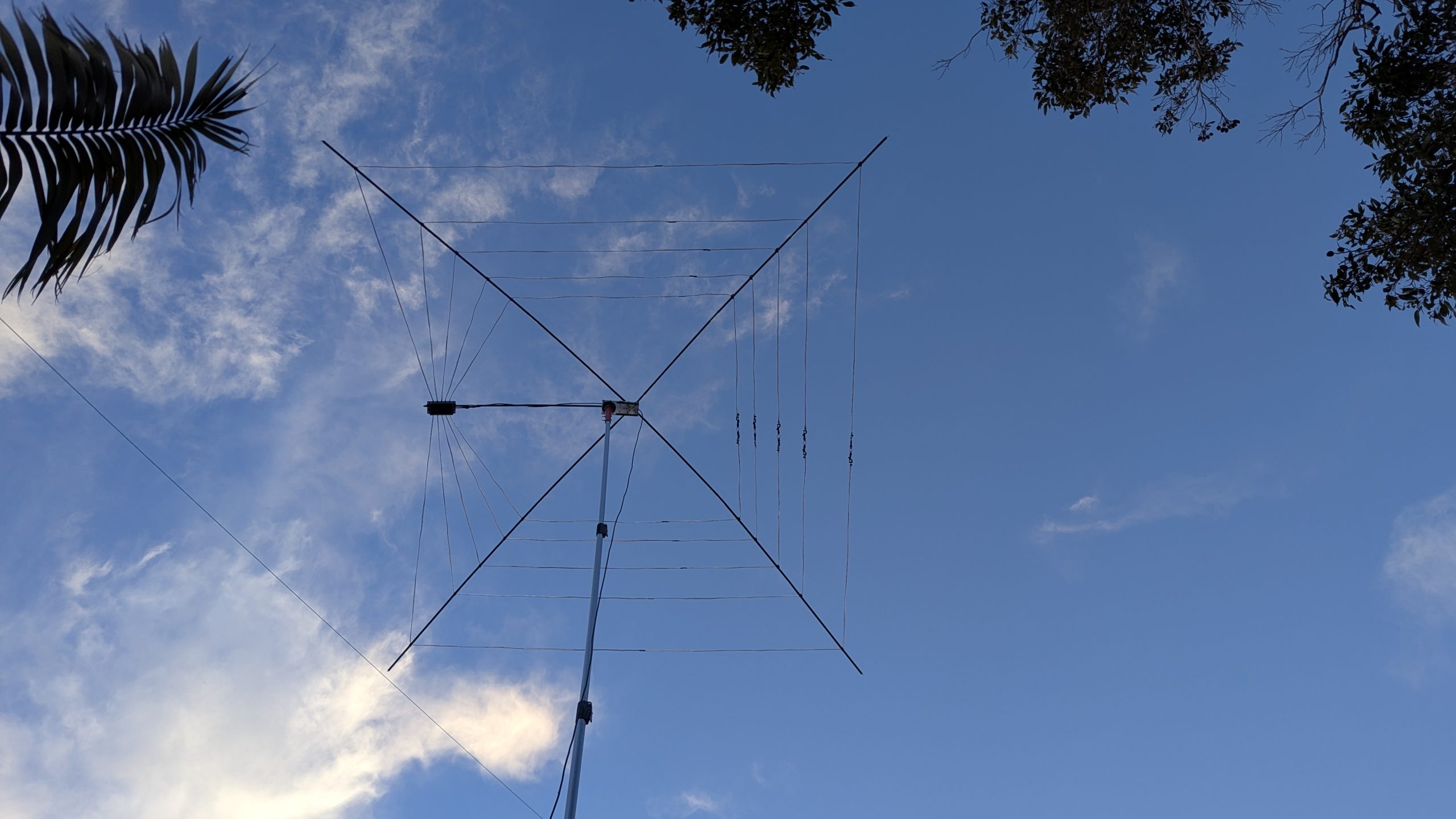
25 Jul Building the Cobwebb antenna
This article describes my trials and tribulations towards building, and understanding, the Cobwebb antenna.
The first thing to note is that there are two closely related designs; the original Cobwebb (note the double-b) that uses folded dipoles with matching stubs, and the Cobweb (single-b) that uses standard dipole elements and a matching transformer.
I built both designs to be able to compare them and settled on the double-b version for reasons described below.
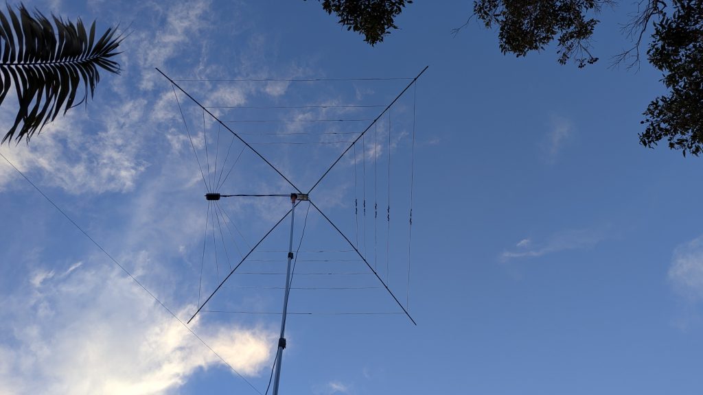
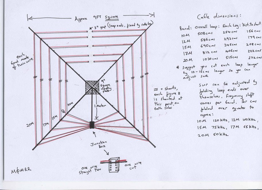
The original Cobwebb design by Steve Webb, G3TPW, features an interesting folded-dipole plus matching stub design.
At first this looked a little daunting as some of the build instructions found online can be a bit vague (or maybe I’m just slow on the uptake).
There is a good PDF by G3TPW describing the design and build instructions, but as his site is not longer working I’ve included a link to it here.
An alternative Cobweb (note the single-b) design was described by Steve Hunt (sk), G3TXQ. This design uses standard dipole elements and a 4:1 matching transformer to bring the impedance up from 12.5 Ohm to the required 50 Ohm.
This version was certainly simpler to build, especially in tuning the radiators. But I was unable to get the match better that about 2:1, even with the 4:1 transformer.
I experimented with several different transformer designs but none improved on the match.
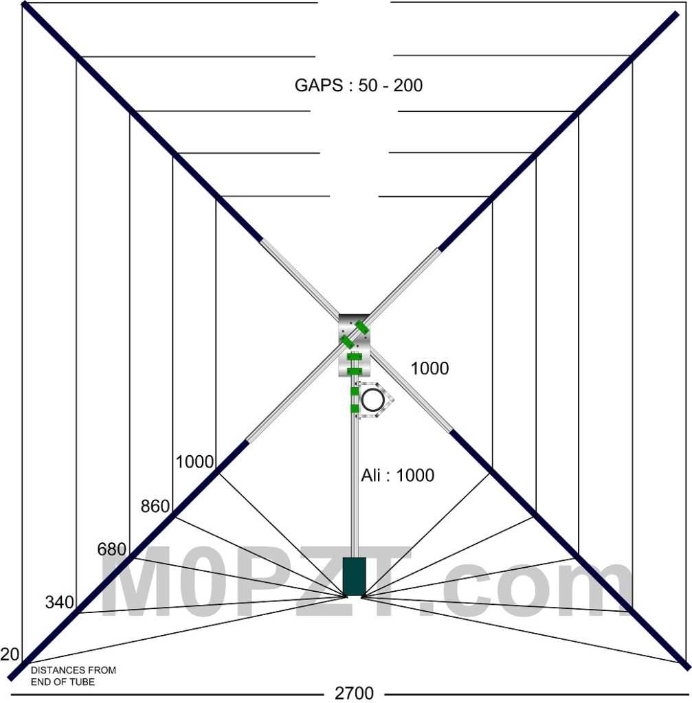
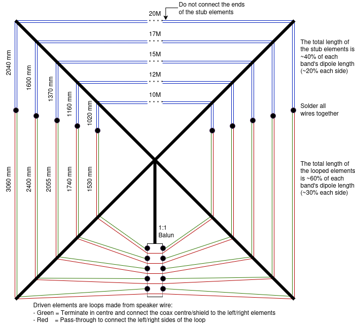
What eventually settled on the original double-b design with the stub matched folded dipoles.
My build was pretty mush per the original design, except that I adjusted the lengths slightly for the target frequencies.
I also neglected the five different gap lengths between the ends of the matching elements, preferring instead to have a consistent gap and connecting design.
I also notice that the ratio of the folder dipole length to the tuning stub length differs between bands in the original design. On 15, 12, and 10 metres the ratio is approx 60%/40%, but on 20 and 18 metres its closer to 55%/45%. I don’t know if that’s important, but I suspect not. At some point I’d like to redo the 20 and 18 metre elements to the 60/40 ratio and find out.
Note the dimensions in this image show the “perfect” 60/40 ratio which I did NOT build yet.
In a similar theme to my Hexbeam design, I built for portability and light weight for field use. This is for temporary use as field days and scout camps.
The materials used as folding fibreglass tent poles, plastic chopping board, and some PVC conduit as the mast attachment.
The antenna takes under 20 minutes to assemble and fits into a shopping bag when done.
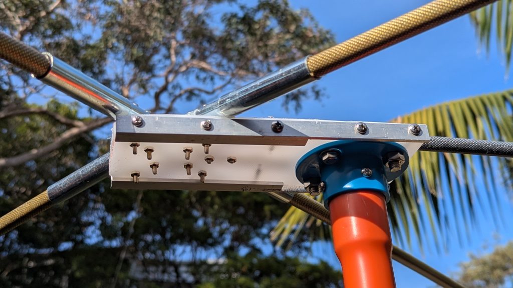
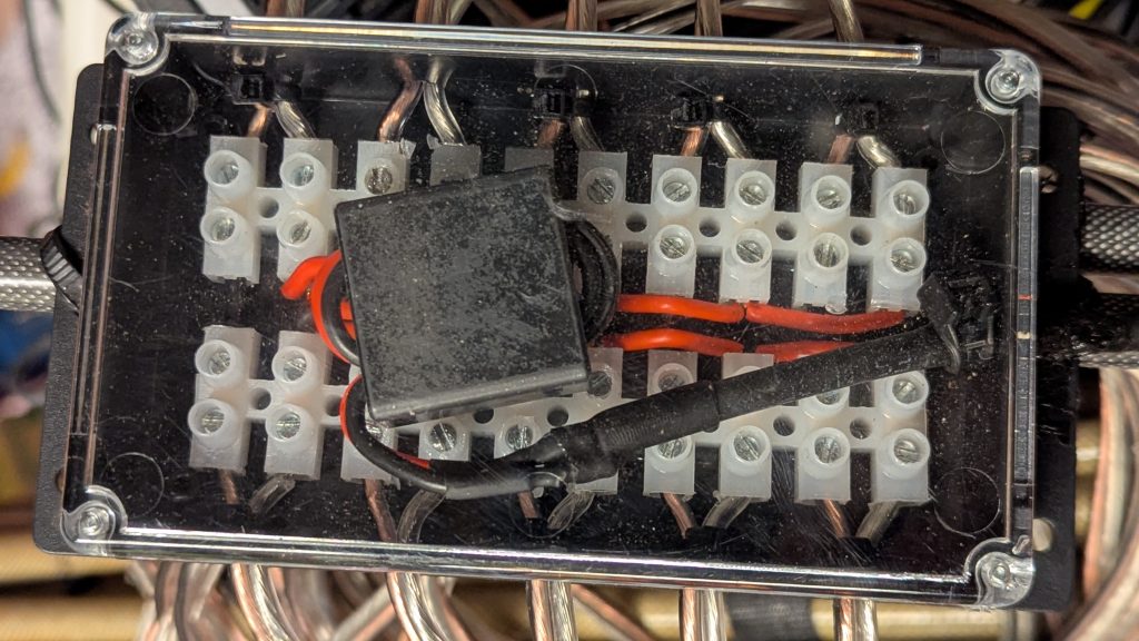
I added a 1:1 choke to the junction box, based on a BN43-7051 binocular ferrite core.
After some initial testing and tuning the the backyard the antenna languished in said shopping bag for many months before I has opportunity to try it in the field.
This photo shows the Cobwebb antenna suspended at about 1 metre height. The red cord is suspended from a rope thrown over a branch above.
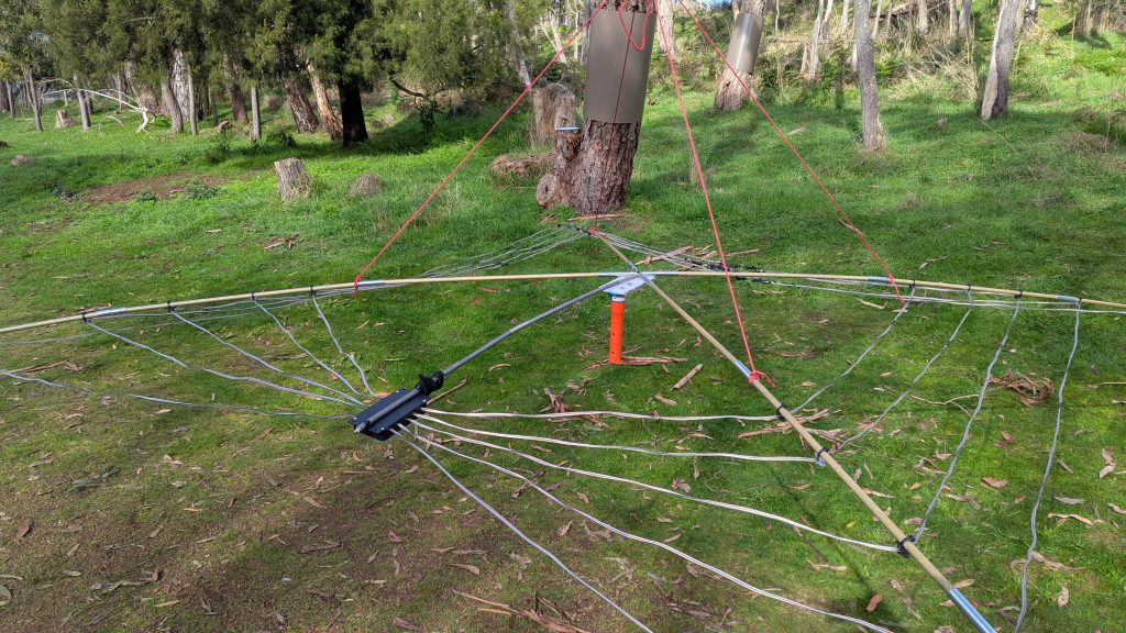
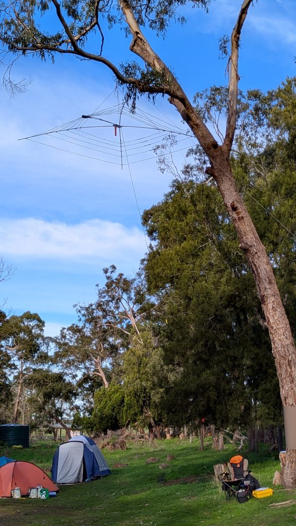
Here it is raised to the highest branch that I could successfully throw a cord and stone over. Approximately 12 metres to the branch, I’d guess.
It had the Scout guessing! Is it a washing line? How did you get it up there?!
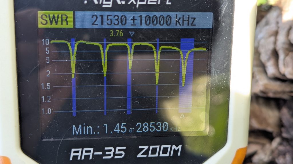
The match was spot on band, though not as low as I’d have liked. Good enough to use the the internal tuner in the FT-450D in any case.
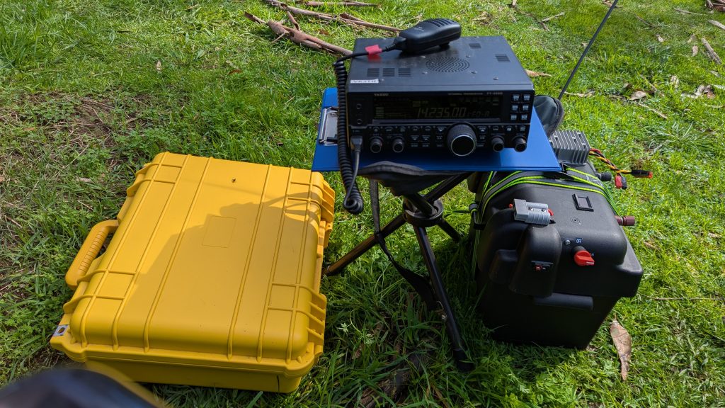
I spend the afternoon making contacts, with the radio balanced precariously on a folding tripod camp chair as I forgot to bring a power cable longer than 30 cm!
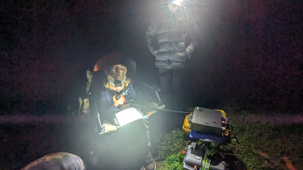
That evening some of the Scouts also had a go, successfully making a few contacts after dinner.
Final verdict?
I was surprised and impressed at how well the Cobwebb antenna worked. In just a few short hours I’d logged QSOs spanning Russia, Austria, Switzerland, France, Portugal, New Zealand, and multiple states in Australia.
Basically, everything you’d want from a portable, multi-band, compact size antenna.
No Comments