22 Apr Random Wire (EFLW) Antenna Designs
Two common, and often confused, types of “end fed” antennas are the end fed half wave (EFHW) and end fed long wire (EFLW or Random Wire). Both are single wire, multi-band antennas but they have one fundamental difference.
This difference being that the former only work when the wire is some multiple of a half wave (thus the name) of the frequencies in question, while the later only work when it is not.
For an EFHW, aligning with the half waves of the multiple frequencies each presents a similar, albeit very high (~2450 Ohms), impedance, which is then easily matched to 50 Ohms with a 49:1 transformer. In comparison, not aligning at the half wave points in the EFLW design also presents a roughly consistent impedance (~450 Ohms), allowing a 9:1 transformer to bring it down to a point there an external tuner can complete the match to 50 Ohms.
For an EFHW the choice of antenna length is relatively simple. It must be a half wave long at the lowest frequency of operation, which then (more or less) aligns with the even multiples of half waves of the other harmonically related amateur bands.
But in the case of an EFLW (Random wire), the choice is far more complex. The length of the wire needs to avoid any (preferably all) of the combinations of half wave lengths and their harmonics on ALL the desired bands of operation. The frustration here is that (as shown in the table) this great list of lengths to avoid tells you little of which lengths to actually use!

Before talking more about EFLW antenna lengths it’s probably worth discussing some designs for the 9:1 matching transformer. Note this is an UnUn, not a Balun, as it is interfacing between the unbalanced coax feed line and the unbalanced antenna.
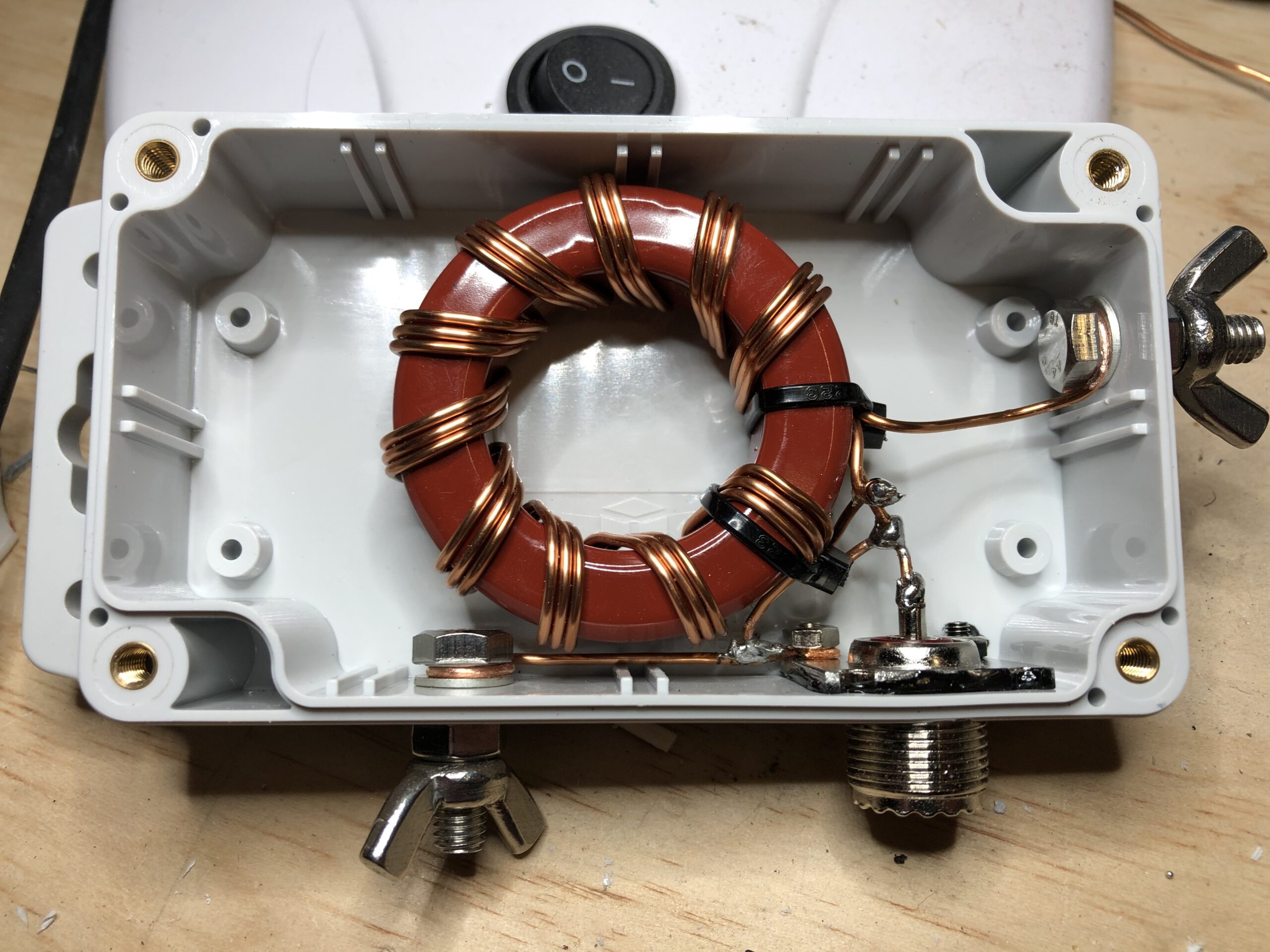
The image with the red toroid is a very common design for a 9:1 UnUn. It uses a T200-2 toroid, which is a 2″ powdered iron core of type-2 material. Around that is wound nine or ten trifilar turns or enamel wire, which looks very fancy but is simply an auto-transformer. There are 30 turns in total, with the primary tapped after the tenth turn. The impedance transformation is the square of the turns ratio (3:1), so 9:1 in this case. This matches the 50 Ohms from the transceiver to the (approximately) 450 Ohms of the EFLW (9 x 50 = 450).
Refer here for more detail on this UnUn design.

An alternative, but close relative, of the above design is shown in the image with the dark grey toroid. This is also a trifilar wound auto-transformer, using a 3:1 turns ratio and giving the same 9:1 impedance transformation. In this case though the toroid is a Jaycar L15 (LO1238) ferrite. This is somewhat similar to an FT140 with type-43 material.
This design gives a better and more consistent 9:1 match across the 1-30 MHz HF bands.
Refer here for more detail on this UnUn design.

Here’s a variation on the above design. It’s wound exactly the same but without an enclosure.
This is connected to a 26 metre (~85′) wire as an inverted-v and works very well. It has been exposed to the elements for over a year now with no problems.

This one is a variation on the same 9:1 trifilar auto-transformer design. It uses a stack of two FT240-31 ferrite toroids and only three turns. That’s a bit of an experiment, as I’d not seen a 9:1 made using the type-31 material before.
This is connected to a 43 metre (~141′) wire as an inverted-v and also works very well.
The question remains though – how long should an EFLW antenna be?
Fortunately for us, and typical for this hobby, much thought has already gone into this question and there are a few pre-calculated and recommended lengths.
One common list (in feet) is: 29, 35.5, 41, 58, 71, 84, 107, 119, 148, 203, 347, 407, 423.
Converted to metres, that is: 7.6, 10.8, 12.5, 17.7, 21.6, 25.6, 32.6, 36.3, 45.1, 61.9, 105.8, 124.1, 128.9.
Note that those are just starting numbers, and factors such as antenna geometry (sloper, inverted-v, etc) and surrounding environment can significantly affect the antenna’s native impedance and its ability to match on any particular frequency.
Refer to the following links for further reading on the recommended EFLW lengths.

The chart shown here (click for a larger view) is my attempt to calculate the relative “goodness” of any particular length of wire for an EFLW antenna.
I took the centre wavelength of each band, divided it into the various antenna lengths, and marked where half wave or near half wave alignment would prevent tuning with a 9:1 UnUn. I also excluded bands where the antenna was less than a quarter wavelength on a given frequency.
The left-most column is a somewhat subjective “quality” factor. Zero is a perfect score (works everywhere), getting worse if the length aligns with, or near, any half waves.
I’ve marked in blue the commonly accepted “good” lengths. These mostly align with what I also calculated to be good, with a few exceptions. Not sure why…?
Looking at the chart you can easily see some good lengths, and some obvious clusters to avoid.
I think it still needs some work, such as tightening up the “bad” lengths for the longer wavelengths, but I think it’s interesting enough to share here. As the statistician George Box said, “All models are wrong, but some are useful”.
.
Aaron Howie
Posted at 20:47h, 14 MayWell explained article, thankyou.