26 Apr The Joy of Hex (beam antennas) – Part 1
This post describes my attempt to build a low cost, low weight, hex-beam antenna for field day use. The intention being to suspend it from a high tree branch in a park.
Part 1 covers the construction details such as materials and dimensions and the initial testing.
The design is based on the G3TXQ Broadband Hex beam by K4KIO but with PVC conduit as the centre post and folding fiberglass tent poles as the spreaders.
Firstly, why a hex-beam? More to the point, why not? With a suburban QTH my regular antenna is a doublet for 80M and higher. And in the field I usually use an end-fed half-wave. I’ve never used a HF directional beam, so let’s find out what I’m missing!
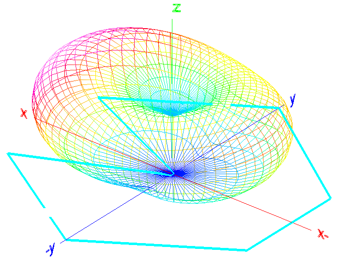
The image on the right shows the far field plot of a single element in the hex-beam configuration. It predicts significant gain at low to medium take-off angles. Potentially very advantageous.
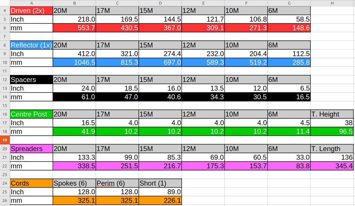
The table below show metric conversions for the bare wire specs from the K4KIO site. This was my starting point.
My initial variance from the K4KIO specification was to use plastic wherever possible for the construction. This was to reduce weight and cost, and to simplify the construction.
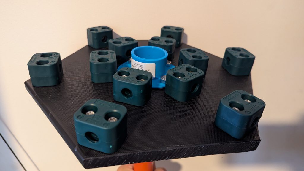
The base plate is made from a 25cm polyethylene chopping board that was then cut to a hexagon shape.
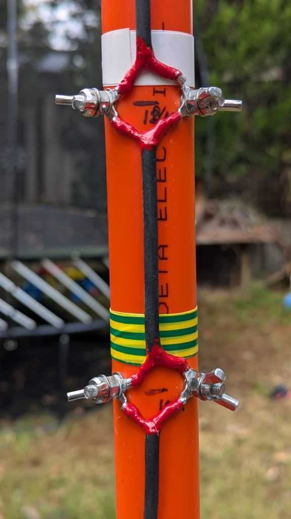
The clamps to hold the spreaders are STAUFF 112A-PP Clamps. Though designed for 12.7mm hydraulic hose I found they present a good interference fit for 11mm tent poles. The poles slide easily into the tightened clamps and are then held fast. This is great for rapid setup and pack-up in field day use.
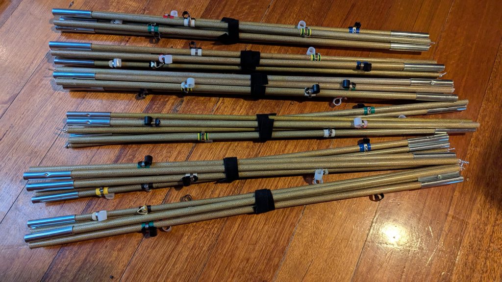
I used elastic jointed folding tent poles for the spreader arms. Again this is to suit field days use and ease of transport.
The first four sections are 11mm diameter and the final two sections are 9.5mm. By reversing their orientation the metal collar on the 9.5mm sections fits neatly into the collar on the 11mm section.
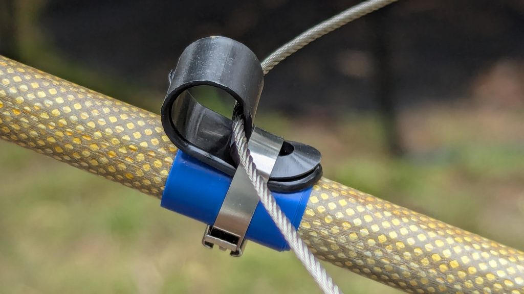
The loops to mount the antenna wires are plastic cable routing clips. I used stainless-steel cable ties to firmly attach these over some colour coded PVC electrical tape. Again, this is to simplify field setup, with each antenna wire having a matching colour code on the wire, centre post, and spreader loops.
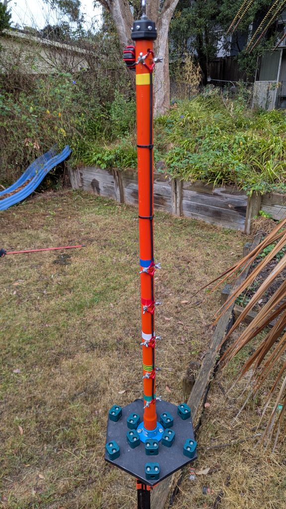
The centre post is made from 32mm PVC conduit. I’m not convinced this will be strong enough but so far it seems ok. Initially it flexed unacceptably during setup, but after glueing and screwing the post into the base plate it seems ok.
With such a flexible centre post it is important to pull up the two opposing spreaders at the same time so the tension is balanced. If you load multiple spreaders all on one side the centre post bends worryingly. But this is only a concern during setup as after all the spreaders are attached it balances well.
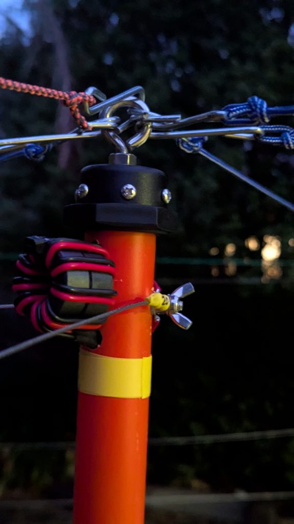
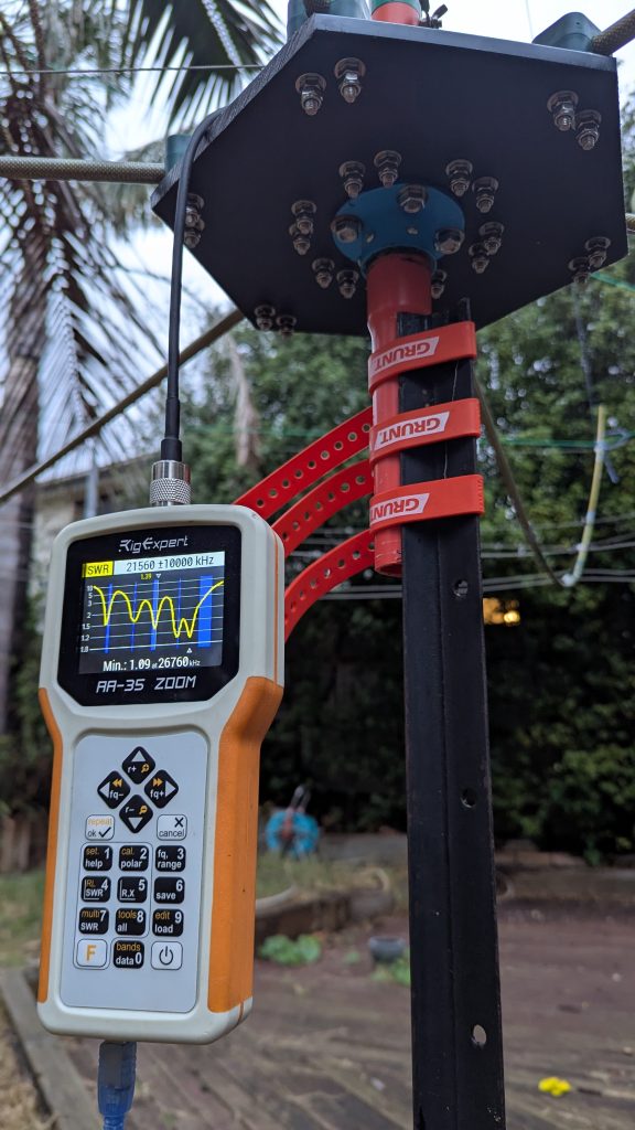
The coax feedline runs inside the centre post to a 1:1 choke mounted near the 20M element. The choke is nine turns on a pair of L15 Jaycar toroids, which should result in approximately 30 dB of common-mode rejection.
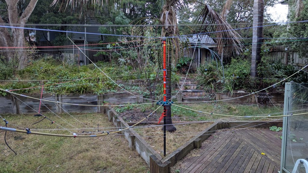
Here’s a photo on my first attempt at assembling the hex-beam at ground level.
I needed to modify some of the support cable lengths to balance the tension. The perimeter cables are simply terminated in a bow-line loop that is quick to slip over the ends of the spreaders.
I used 1.5mm stainless steel wire for the antenna elements.
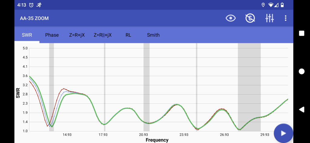
So, does it work? That’s yet to be proven, but it tests ok for a first approximation. There are good dips at most of the target frequencies. I had to trim the 20M element (as shown in the scan) to hit the band, cutting 6cm from each of the driven elements and 12cm from the reflector. Not shown here is the 6M band which had its best match at 50.6 MHz.
Stay tuned for part 2 where I will attempt to hoist it into a tree and test its operation on the air.
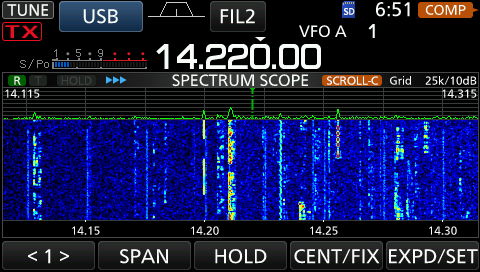
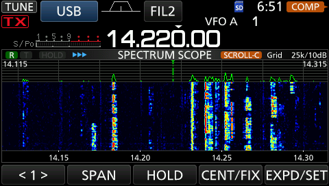
Finally, here’s a comparison of on-air performance. The first image (with the higher noise floor) is with my doublet, approx 42M of wire over the house and approx 12M above ground at the peak. The second image (with the lower noise floor) is the hex-beam at ground level, pointed vaguely north-east from Melbourne. Listening to FT8 suggests at least one S-point (~6 dB advantage to the hex-beam.
No Comments