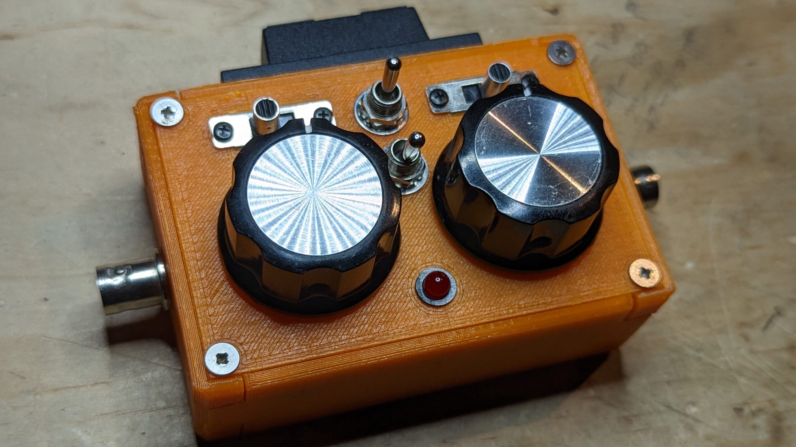
27 May Tiny z-match tuner for the (tr)uSDX transceiver
This post describes the design and construction of a small manual z-match antenna tuner to compliment the (tr)uSDX transceiver.
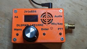
The (tr)uSDX is a small, inexpensive, QRP transceiver designed by PE1NNZ and DL2MAN. It is available as a kit or can be ordered pre-built. It has approximately 5W output, with three RF options available; low bands (80, 60, 40, 30, 20), high bands (20, 17, 15, 12, 10), and classic (80, 40, 20, 15, 10).
After seeing an online post where someone had build a manual tuner to fit in the same form factor I wanted to attempt building my own version.
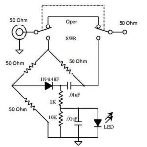
I started with a z-match design that I’ve used previously. I adapted that per one of the design’s references, adjusting for the smaller capacity of the polyvaricons.
I also included a variation on the Tayloe SWR indicator bridge, opting for a design without the small toroid. I liked this version as it was simpler to build and I could layout the components to suit the case constraints.
I dusted off the old 3D printer and modified the STL files for the (tr)uSDX case to suit the z-match controls. I printed the two shaft extenders to connect some plastic molded knobs to the polyvaricons.
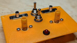
The controls are (from top, left to right):
- DPDT slide switch – to select the SWR indicator.
- DPDT toggle, centre-off switch – to select the C1 capacitor ranges (C1.A, C1.A+B, or C1.A+B+470 pF cap.
- DPDT slide switch – to change between balanced line and BNC output.
- DPDT toggle switch – to change between the high Z or low Z secondary on the toroid.
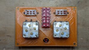
Flip side of the top panel showing the various switches, LED, and the two variable capacitors.
The variable capacitors (polyvaricons) are model CBM-443BF, sourced from here.
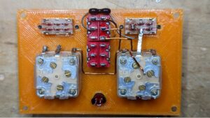
Before assembling the rest of the case I connected the first DPDT toggle switch to the C1 capacitor and the 470 pF silver mica cap as shown.
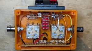
Next, assemble the case and connect the SWR indicator circuit and other connections as shown.
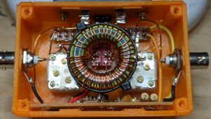
Note the solder blob in the centre of the SWR circuit that will be used to ground the inductor in the next step. In this photo you can also see the connection for the balanced line on the top side of the case. I used a spring loaded bracket for its physical robustness.
The fiddliest step in the construction is connecting the inductor. It is connected to the ground point described above, and to the C1 and C2 variable capacitors.
Adding the switchable secondaries, one with 16 turns and the other with 4 turns, means having to connect to the second DTDP toggle switch that can be seen through the toroid centre.
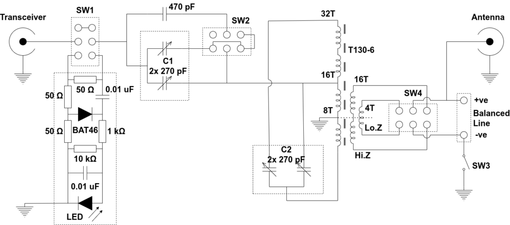
This is the circuit, pretty much as-built, though I substituted a couple of resistor values for components that I had on hand.
Finally, does it work? I’m glad to say the answer is “yes” and very nicely too.
The benefit of the Tayloe-style SWR indicator is that while tuning the transceiver never sees more than about a <2:1 ratio no matter how bad the match initially. The LED goes out when the match is good. After tuning then you switch the SWR indicator out of circuit and should see a usable SWR ratio.
In practice it only takes a few seconds to tune any band to an acceptable SWR (<1.5), and with a bit more effort it can get near to 1:1.
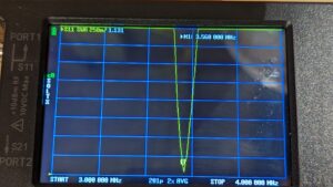
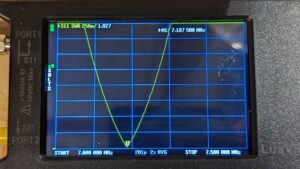
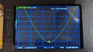
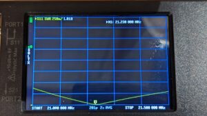
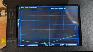
In summary, a fun build that only took a few hours after I figured out what I was trying to do.
Next I’d like to better understand the design, to be able to model its performance and adjust for changes.

Alan Campbell
Posted at 13:44h, 30 MayMy word, that is a compact design. Bravo!
Since you 3D printed the box, you could have added some labels.
You could also try a thin sheet of perspex to add on top, where you mark knob positions. Probably would only be good for one antenna, but gives you a rough guide when setting up a band.
Kudos again for a great build.
Steven Pemberton
Posted at 19:02h, 03 JuneHi Alan,
I probably should have added labels, at least for the switches. The SWR indicator LED makes it very fast and intuitive to tune though.
James Rogers
Posted at 13:53h, 04 AugustWill you please post a parts list with where you sourced some of the parts?
Steven Pemberton
Posted at 12:14h, 25 MayHi James,
All the parts should be pretty common and easy to source.
The variable capacitors are 270 pF model CBM-443BF that can be found online (e.g. AliExpress).