
17 Dec QDX – Digital Transceiver
The QDX is a 5W, 4-5 band (80, 40, 30, 20, and 60) transceiver that’s manufactured by QRP Labs. It’s available in kit form with the SMDs and ICs pre-soldered or fully assembled.
It has a number of interesting features, not the least of which is that it only supports single tone FSK digital-modes. That includes everything in WSJT-X, and JS8Call, RTTY, etc. There is no capability to transmit SSB, in fact the digital modes are not driven by audio being modulated on SSB but are instead synthesised directly.
For more information refer to the QRP Labs website: https://www.qrp-labs.com/qdx.html
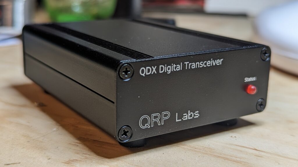
Assembly
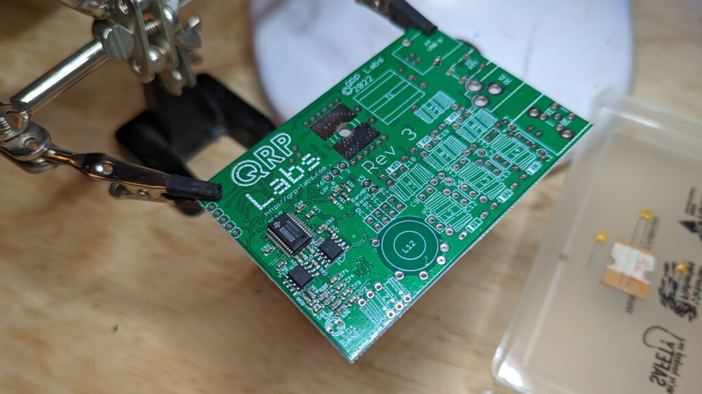
View of the board as delivered.
The first step is to mount the various through-hole components. Easy to do, though there is a fair variety and plenty of holes to use by mistake!
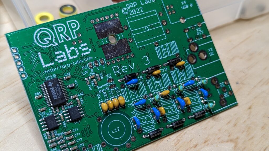
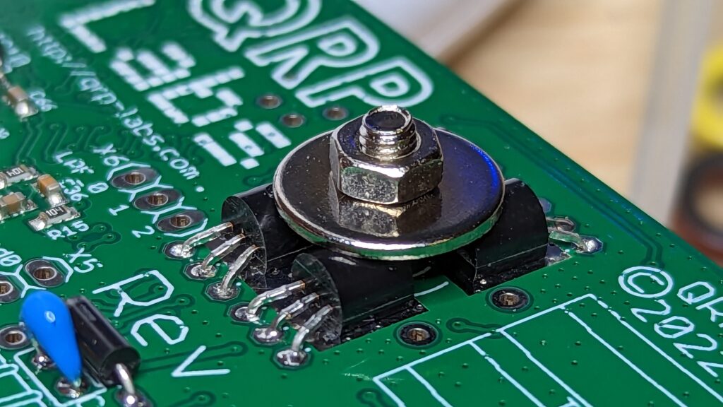
Then mount the four BS170 PA transistors. Bend them as shown and firmly clamp them to the PCB with the supplied washer and nut/bolt.
You need to decide on the power supply voltage that you want to use when winding the binocular transformer. This can either be 3:3 ratio for a 9v supply, or 3:2 ratio for 12v.
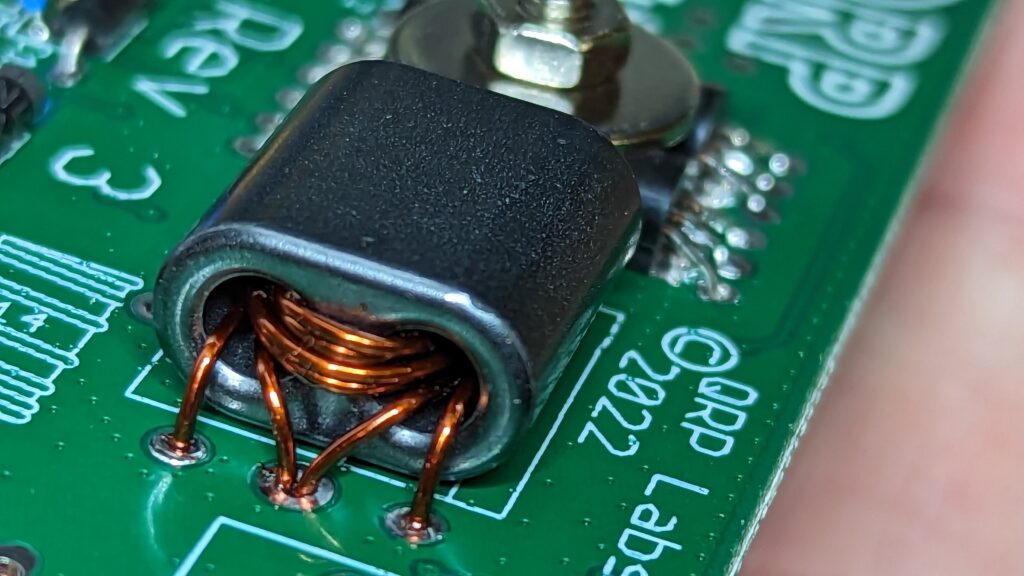
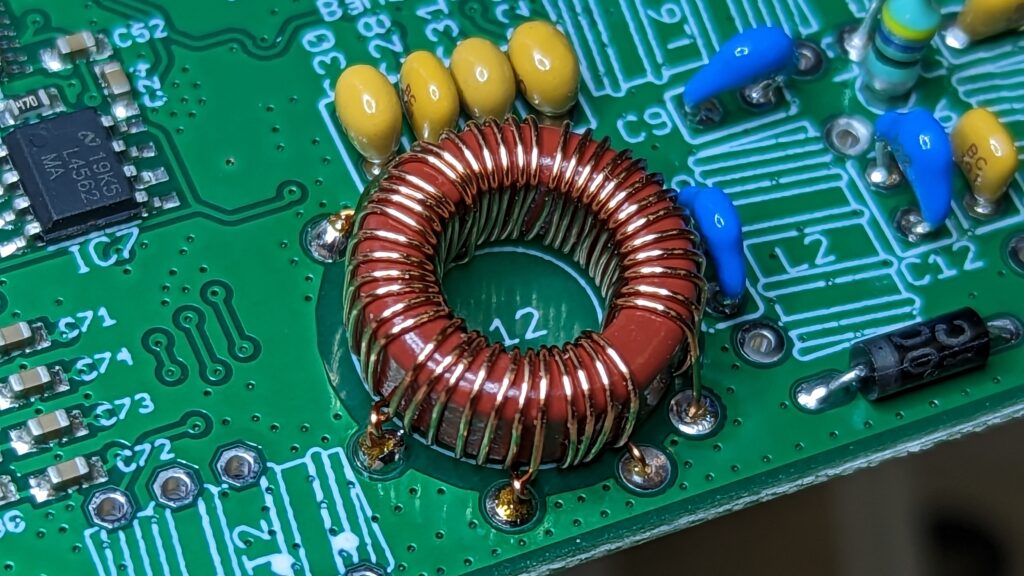
The most complicated step in the assembly is the multi-tapped T50-2 shown here. It is however easier to work with than most of the other inductors as it is relatively large.
The rest of the inductors are very fiddly, using T37-size toroids. One is even a ten turn trifilar.
These were awkward to solder and I needed to use hot glue to hold them in place before applying solder to the leads.
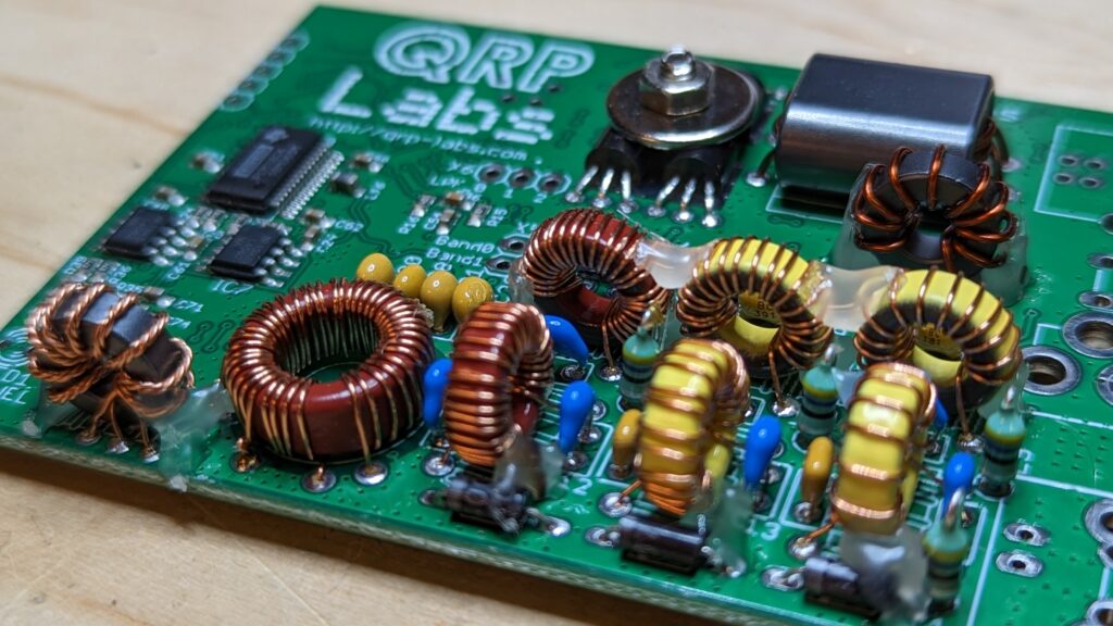
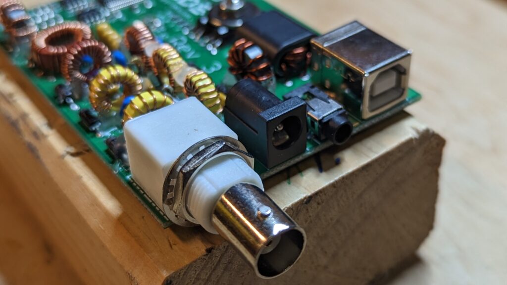
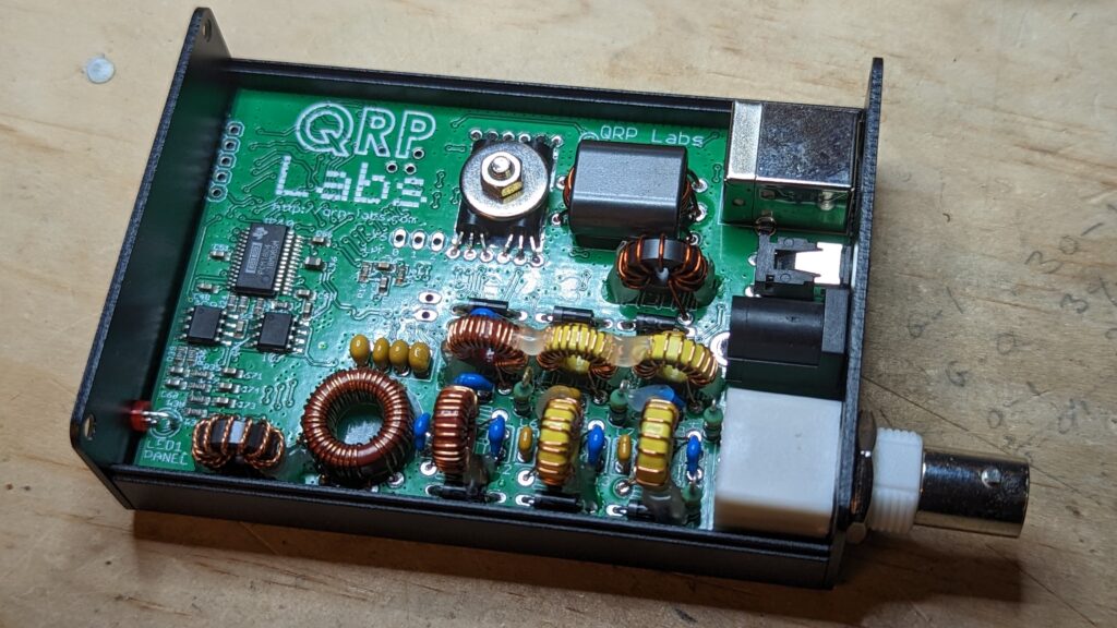
Mounting the various sockets was straight-forward.
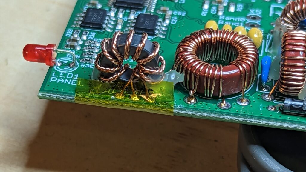
Mount the LED as shown. I also added some polyimide tape to the PCB edge beside the trifilar toroid as I was concerned the solder pads could short on the aluminium case.
Finally, slide it into the supplied case!
Operation
When I first tried using the QDX with WSJT-X on my main PC I thought I had a problem. It was receiving OK and decoding digital modes, but there was zero RF output on transmission.
So I took it back to the workbench and touched up a couple of questionable solder pads, but still no RF output…
Then I connected it to a different PC running WSJT-X and found that it worked fine! 5-6W output on the workbench PC, but still 0W on my main PC.
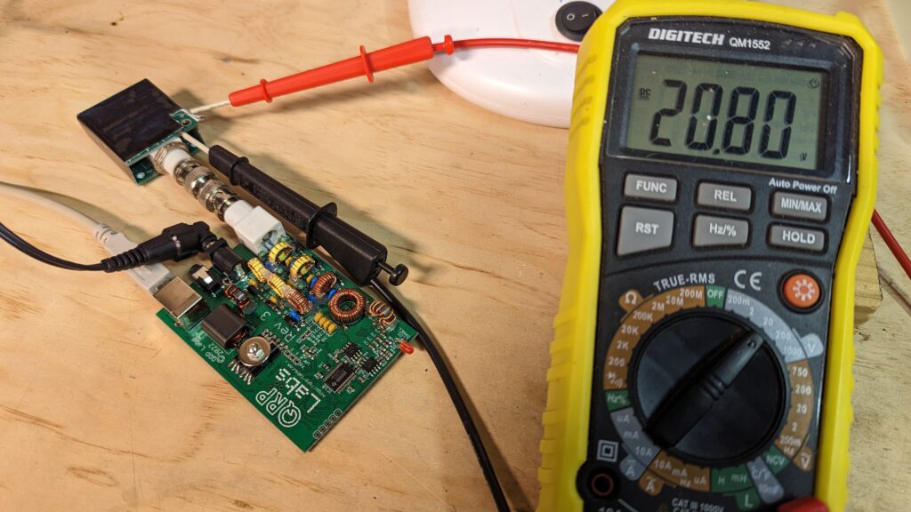
After a bit of head scratching, and double checking the WSJT-X settings, I reasoned that there must be something wrong with the PC’s volume settings for the QDX’s inbuilt USB audio adapter.
So I installed “pavucontrol” (since my PC runs Linux) and, as predicted, the QDX volume was set to zero. After changing that to 100% everything worked as designed.
As I type this it’s happily logging WSPR spots, Tx & Rx, into the USA and Canada.
Tuning
The QDX includes a serial terminal for configuration and tuning. This is not needed in normal operation but is worth checking on a new build.
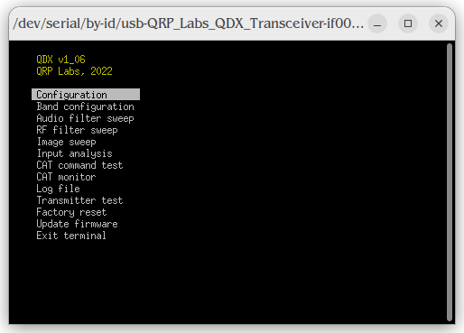
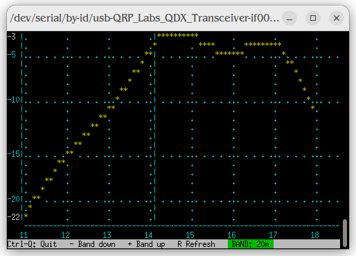
One of the more interesting configuration screens tests the operation of the band pass filters. You can then adjust the turn spacing on the inductors to optimise its performance.
That’s my next job. Updates to come…


No Comments