14 Dec The “uTurn” A “minimum parts count” Remote Control
by Jim Sosnin VK3JST
Here’s an idea that might fit a variety of applications, especially if you’ve constructed some gadget that has to be located away from your operating desk, but nevertheless has a control that you need to access easily. A simple “minimum parts count” remote control.
It all started when I was experimenting with a homemade manual antenna tuner that I’d mounted halfway up the wall, to be closer to the entry point for a ladder-line feeder. ‘Ladder-line’ is doubly appropriate here, because I almost needed a ladder to reach the tuner! And whilst it’s very easy, these days, to extend one’s reach by using a rotary encoder and a stepper motor connected via an Arduino, or similar device, this seems like overkill for a manually operated control.
I wanted something that would cost no more than a few dollars, and that I could hack together in an hour or so. I didn’t need to worry about counting steps, or even including limit switches, as the fine-tune capacitor whose shaft was to be turned had free rotor plates with no stops. The result is this ‘minimum-parts-count’ Remote Control, using a cheap rotary encoder controlling a cheap, small stepper motor directly via the stepper driver board, which comes supplied with the motor. This is possible even though the encoder output is just two-phase, and the stepper expects four ‘phases’ on four separate wires. Fortunately, the 2-bit Gray code generated by the encoder is exactly what the stepper can use directly, albeit in only one of its drive modes, where two of the drive phases are simply inversions of the other two.
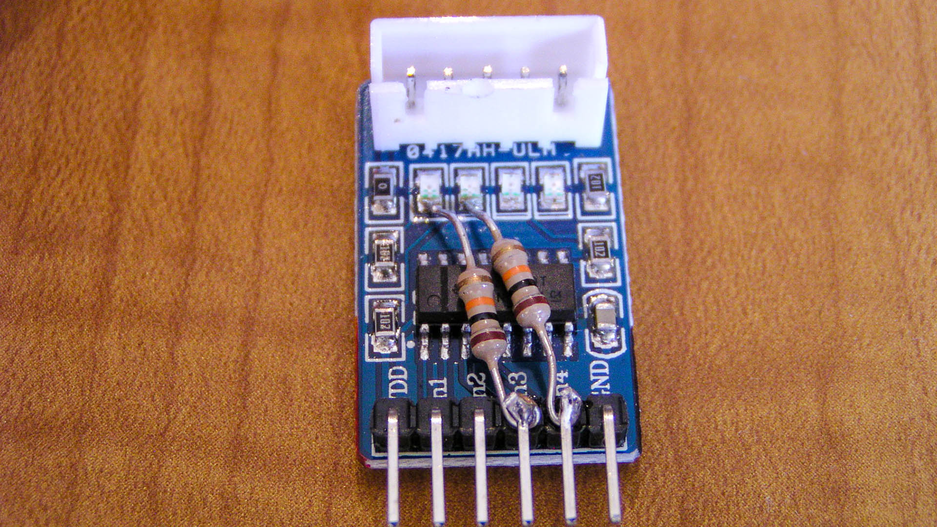
The driver board pictured uses a ULN2003 IC containing an array of Darlington transistors, connected for collector output, so there is a logic inversion from input to output. To get four drive signals from the two incoming, all that is required is a simple modification to the driver board: two 10K resistors connecting from outputs 1 and 2, to inputs 3 and 4. For the photo of this mod, I mounted these resistors on the top of the board, but in practice, it is easier to mount them on the underside of the board, on to the solder pads around the input and output pins of the connectors.
The main photo, and the schematic, show the power supply, ie the battery, at the ‘manual control’ end of the cable. I wanted to be able to switch the power off whenever the motor was in a stopped state, to extend battery life. In other situations it might make more sense to locate the power supply at the ‘slave’ end of the control cable, to reduce voltage drop to the stepper motor, especially if it’s a larger motor. Also, if it’s an direct-drive stepper motor, it may need power applied at all times, even when it’s stopped, to prevent slip.
The rotary encoder and the small 5V geared stepper motor, complete with driver board, can be found on eBay for just a few dollars each. You’ll find them if you include ‘Arduino compatible’, as search keywords, since they are used in lots of Arduino projects. If operated from a battery, either 4.5V or 6V is fine, as the only active components are the Darlington transistors in the driver IC. The LED and its series resistor are optional. I included the LED as a reminder to switch the power off between tuner adjustments!
Finally…
That’s all there is to this simple remote control. I wanted to call this project the ‘iTurn’, but became concerned about the possibility of a lawsuit from an Apple, so I did an about-face and settled on ‘uTurn’
Parts
At the time of writing, there are plenty of places to get the parts for this project. You’ll find a lot of sellers offering combo packs and quantity UNL2003 boards on eBay. Jaycar sells a stepper motor as well as a Rotary Encoder with Pushbutton and there are other businesses such as Aus Electronics Direct that sell a 5v stepper motor and rotary encoder.
It doesn’t matter where you call home, why not become a member of SPARC. Join today.


Posted at 22:09h, 14 October
A great project with lots of potential Jim well done.
Mark Bruechert
Posted at 11:38h, 15 OctoberThis is a great idea, thanks Jim.
Tony Falla
Posted at 14:06h, 18 OctoberGreat idea Jim